The hobo’s guide to exporting vector graphics from Adobe Shape Creative Cloud
Adobe Shape CC is a free mobile app for vectorizing high contrast images. It’s good for generating crisp graphics from sketches. (See my prior post on a similar process using old school tools.) You can export the results as an image directly from the app or retrieve images as free assets from Adobe Creative Cloud. However, to access editable vector versions of your designs, you need a paid Creative Cloud subscription and/or Adobe’s desktop software.
Sort of.
Using a modern desktop browser, right click an asset thumbnail and select Inspect Element to poke around the associated code in the browser’s developer view. Locate and copy the associated background-image URL:
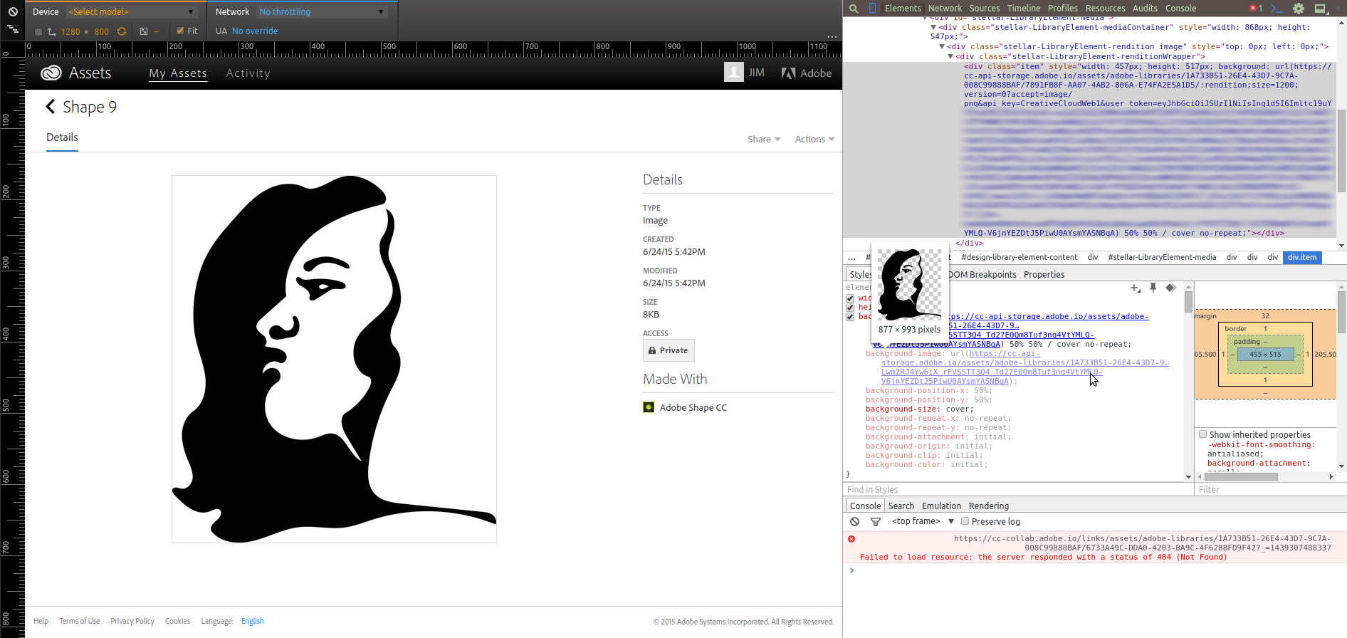
This URL requests a PNG image based on the underlying shape. However, you can edit the URL to retrieve the raw SVG of your artwork. Initially, the URL will look something like this:
https://cc-api-storage.adobe.io/assets/adobe-libraries/[ASSET_ID]/:rendition;size=200;version=0?accept=image/png&api_key=CreativeCloudWeb1&user_token=[USER_ID]
Delete the underlined portions to locate the vector version. You may need to use your browser’s Save As feature if the SVG is displayed instead of downloaded. Be careful to retain the long ID strings and the question mark delimiter (?). Now you can revise the vector artwork you created on the go using a free program like Inkscape.
Here’s a hint to roll your own browser bookmarklet to do this with one click:
Posted on Tuesday, August 11th, 2015. Tags: art.
9000 mile bike check
I recently hit 9000 miles on my bike. I get more fun and function out of it than ever these days. In the spirit of acknowledging good gear, here are a few notes on noteworthy components.
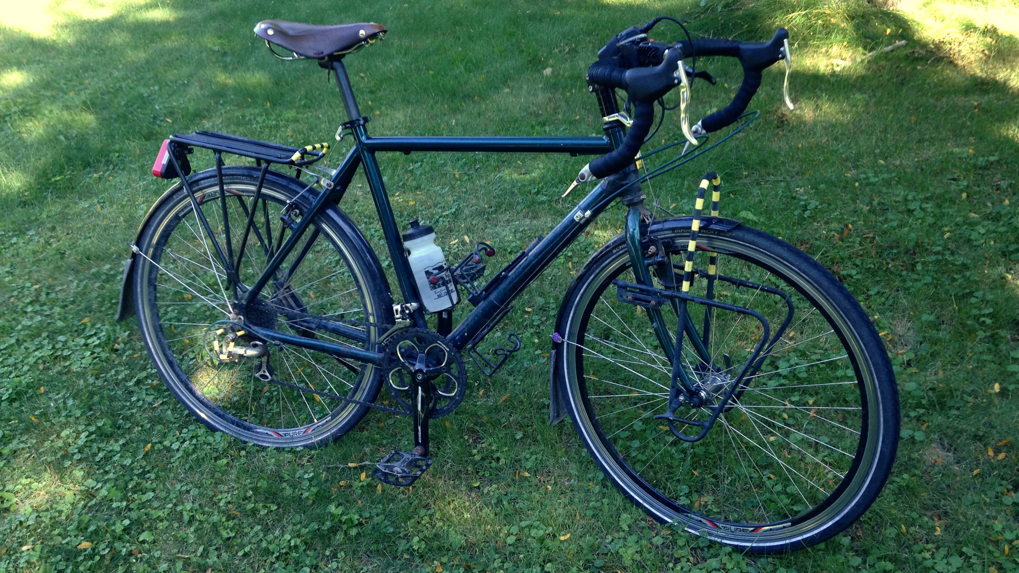
It’s built around a Nashbar aluminum touring frame, which sadly no longer seems to be sold. It was only $99! People ask what makes it a touring frame. Two things, in my experience: first, lots of hardpoints for mounting useful stuff like racks, fenders, and bottle cages, and second, it’s got a slightly longer wheelbase than a “racing” road bike. The stretch is subtle but easiest to see if you look at the gap between the wheels and the seattube/downtube. The extra length provides plenty of clearance for accessories and baggage.

Tires are venerable Schwalbe Marathons in 700c x 32. They’re not cheap but they are bulletproof. These tires have absorbed hits that would burst lesser tires and have chewed up and spit out debris would that perforate lesser tires. I know: the first set of tires I had on this bike lasted less than a thousand miles and suffered constant punctures in city riding. I think I’ve only had four or five flats in the remaining 8000 with these (and some of those were due to valve stem issues).
The wheels are Pure Tour 700s from Bicycle Wheel Warehouse. They are built for durability with 36 spokes and deceptively deep and beefy rims. No broken spokes and still perfectly true.
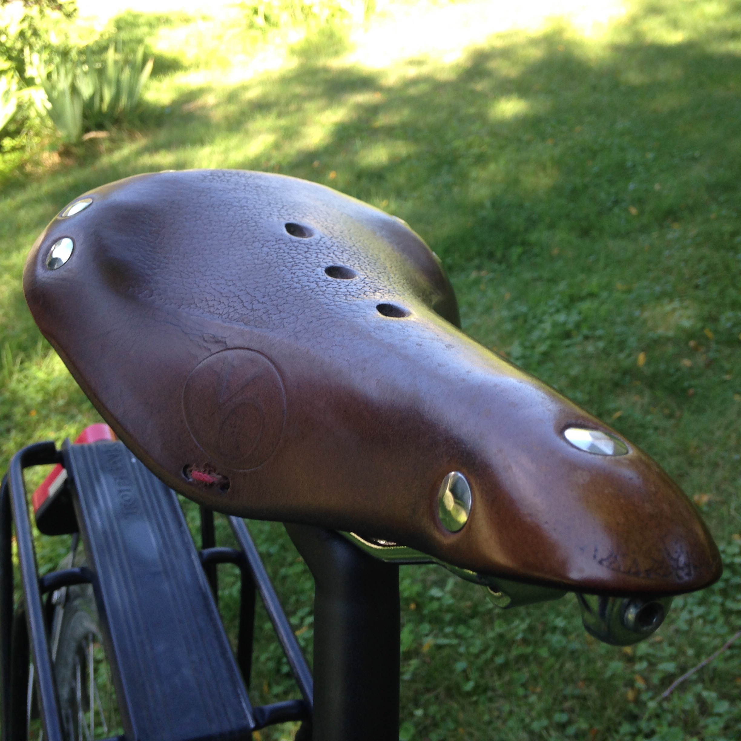
The saddle receives a lot of comments. It resembles a vintage Brooks but is in fact a Velo Orange Model 3. What’s the deal with leather saddles, you ask? (Many people do.) True, the surface does not feel as soft as the foam coating conventional bike seats, but unlike those seats, there is no rigid platform beneath the surface: the leather is strung like a hammock between the front and back. It fully conforms to your butt and grows increasingly supple over the course of a long ride.
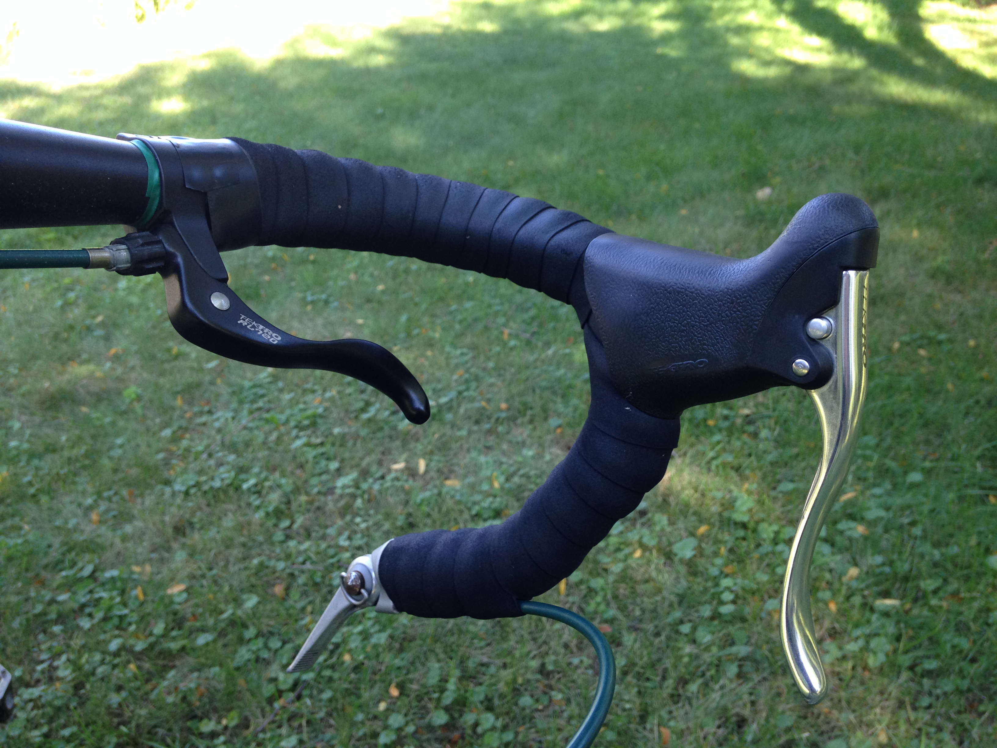
Cockpit levers! Cyclocross-style inline brake levers on the top of the bars maintain control even in relaxed upright riding. Old school friction shifters are not gonna win any drag races but are endlessly adjustable and provide the bicycle equivalent of stick shift street cred (or so I suppose). The one fault with this setup is that the bar-end shifter location is subject to the occasional inadvertent bump. I dig the Gevenalle (née Retroshift) solution of mounting friction shifters on the brake levers – something I still consider for the future of this bike.
Posted on Friday, July 31st, 2015. Tags: bike.
Import STL Models to Onshape Part Studios using FreeCAD
Onshape is a sweet new parametric CAD system that runs in your browser. It can import designs from various CAD formats, but it cannot import the ubiquitous STL format popular in the 3D printing world. (Technically, it can indeed import any file type, but only for storage; only select formats can be converted to an editable part studio.)
I don’t know jack about FreeCAD, a cross-platform desktop CAD system, but it can be used to convert STL files to another format (STEP) that can be successfully imported into Onshape.
Posted on Thursday, July 30th, 2015. Tags: 3d.
Combining Course and Terrain Models with Boolean Modifiers in Blender
I don’t know jack about Blender, the free 3D modeling program, but I have found it useful for combining pieces of my 3D printed landscape models. It performs boolean operations quickly and produces clean output (valid STL files). However, the interface is notoriously intimidating to new users – myself included – so here is a screenshot-illustrated guide to the process I’ve worked out to make a few types of route + landscape models.
This is not a general-purpose tutorial. It is focused on the task of combining an STL terrain model with an STL course model. Both inputs are assumed to exist and to be pre-aligned at the same scale and orientation. (I will explain my process for creating those models in a subsequent tutorial.)
Posted on Thursday, July 30th, 2015. Tags: 3d, geography.
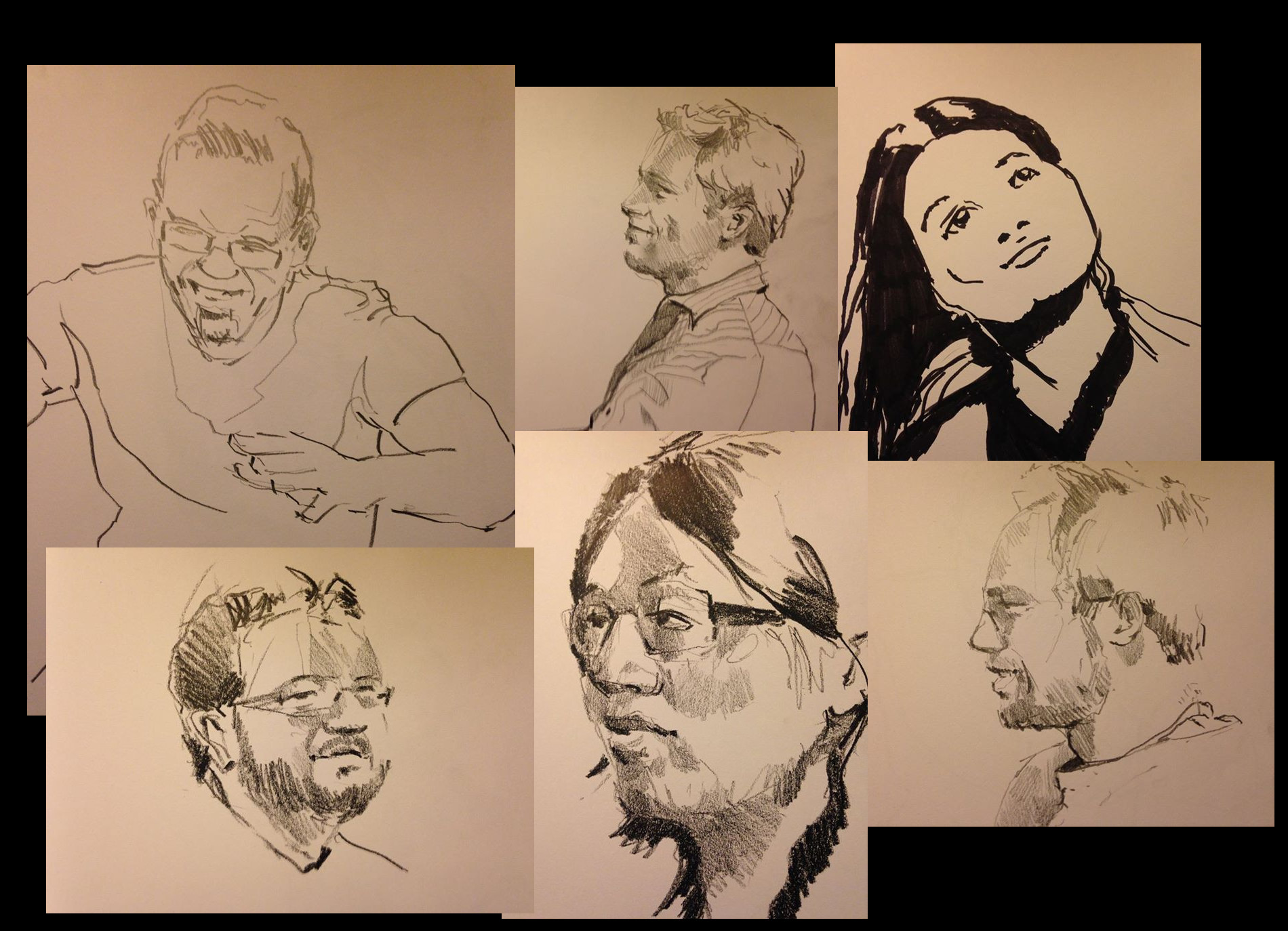
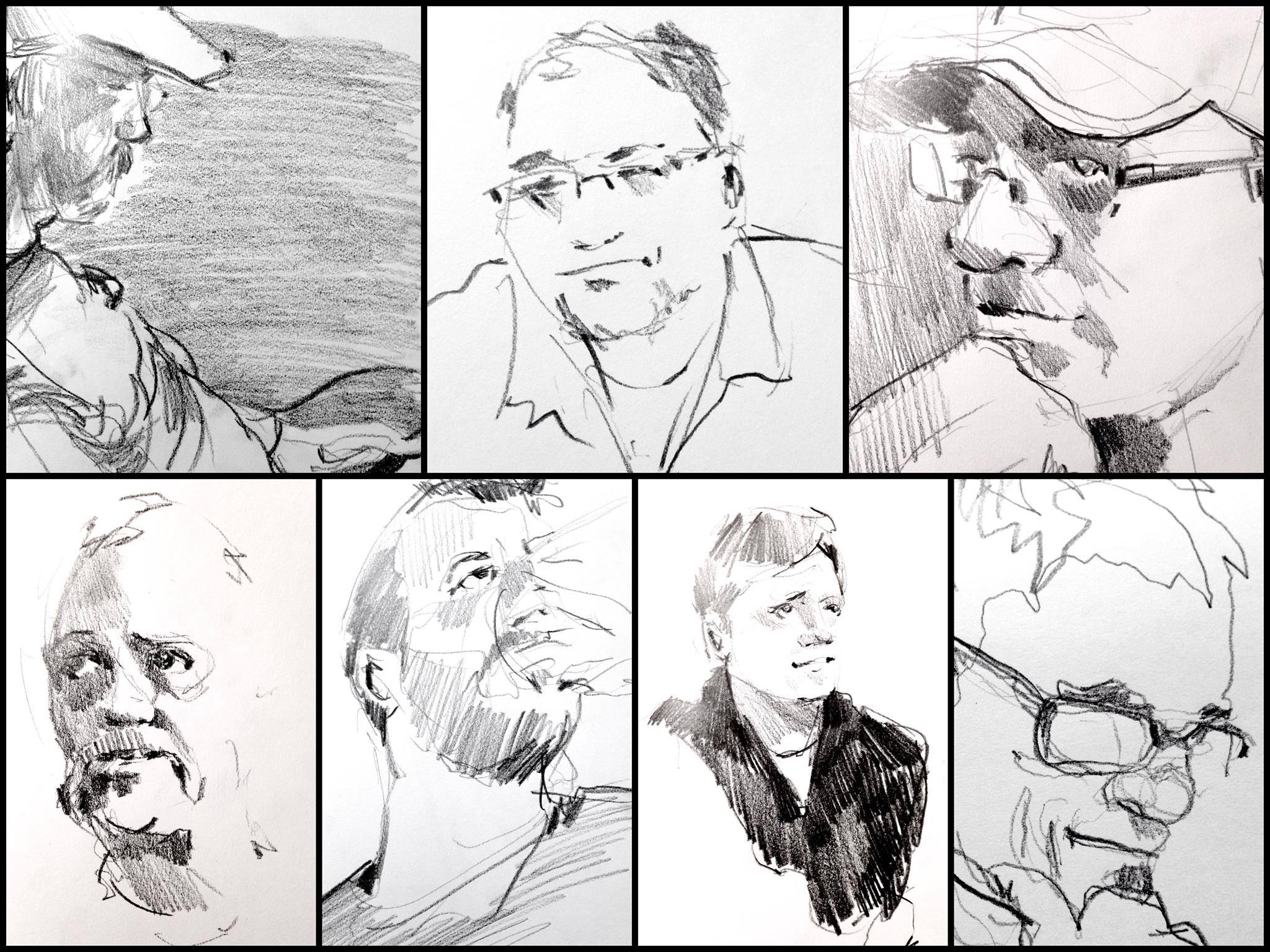
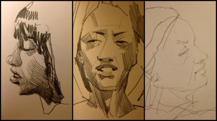
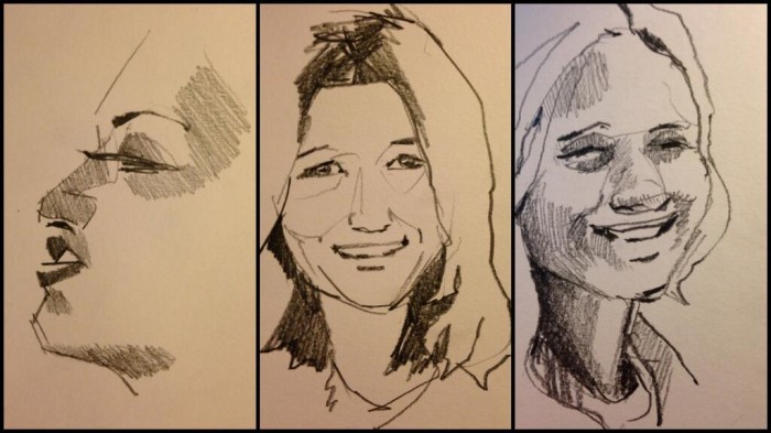
Portrait Sketches
Some random portrait sketches from this summer:
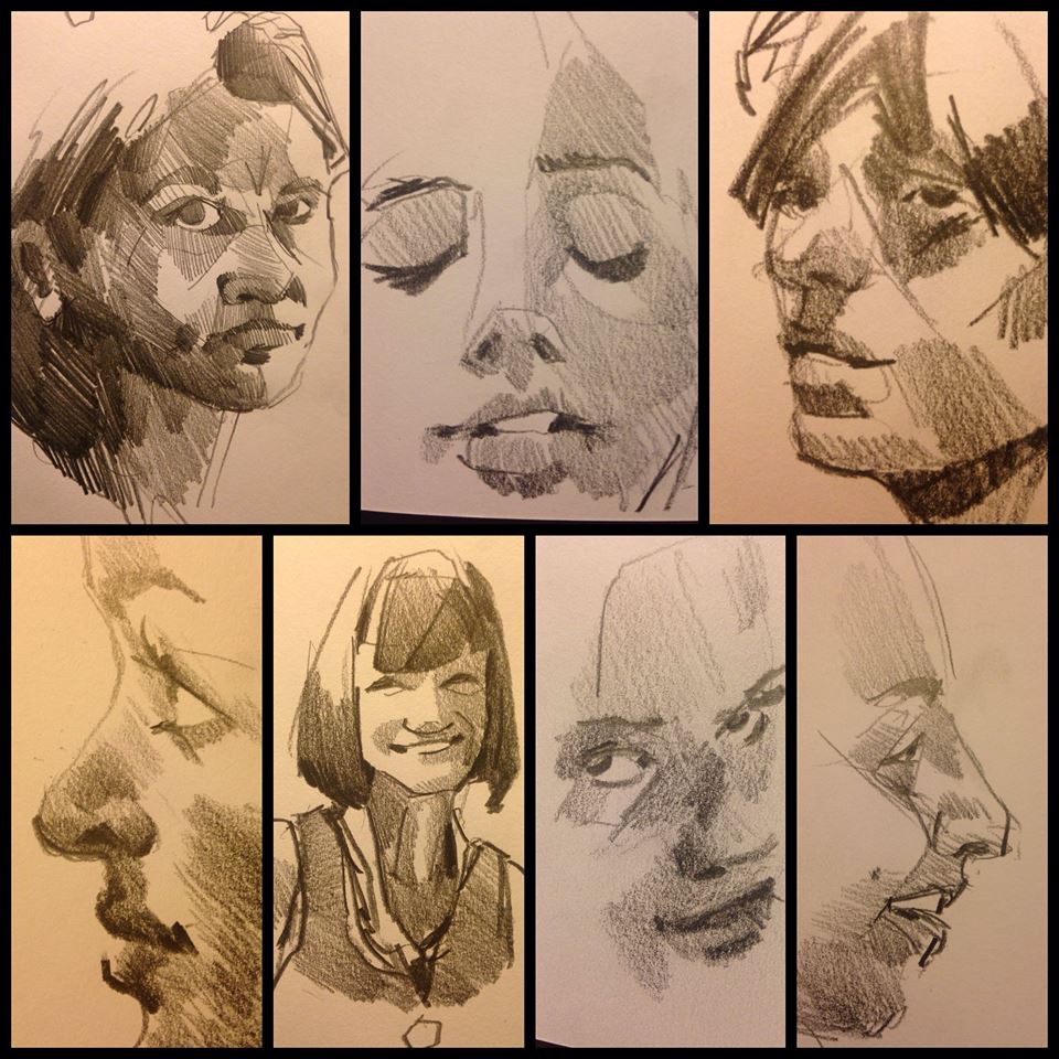
A fun development this fall was discovering Fear of Art, a group founded by some high school acquaintances. They organize monthly “Drink and Draw” events that are a great way to get a little experience life drawing. I’ve attended two so far. Here are some of the pictures I drew at the September and November meetups, respectively:
Posted on Wednesday, December 10th, 2014. Tags: art, drawing.
Status Update
Since this spring, I’ve been going to the library a few times a week to serve as a Literacy Volunteers tutor. Monday morning Math Lab and, more recently, Wednesday morning Reading Roundtable have become a regular part of my schedule. It is not something I would have foreseen myself doing a few years ago, but it has proven to be a very positive experience. Lots of fractions.
In late October, I began working for the local Urban League’s after school program. Even more than tutoring, it is a new challenge with new rewards. My job is a combination of homework help, playground supervision (I’ve played more kickball in the last month than I have in the last 30 years), and driving a passenger van.
Posted on Wednesday, December 10th, 2014.
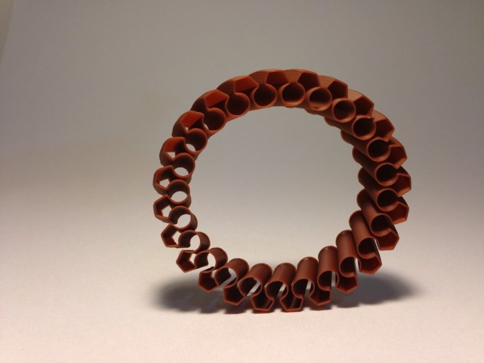
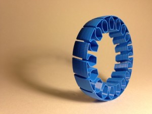
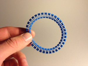
Stretchy Bracelets
Inspired by some similar designs, I designed a pair of customizable bracelets. They get their flexibility from their many folds. Even printed in relatively brittle PLA (the brown material), the small amount of flex that can be coaxed out of each kink adds up to make the whole thing pretty elastic. The blue material is a PLA/PHA compound that is even more flexible and durable.
Posted on Thursday, April 24th, 2014.
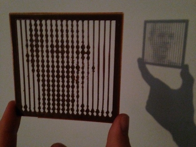
Shadow Casting Photo Panels
I designed a customizable thing that converts a photo to a printable panel. The size of each pixel in the panel varies according to the brightness of the corresponding pixel in the image. The pixel shapes are connected and held in place by thin strips, kind of like beads on a string. The idea is that when viewed at a distance, or as a cast shadow, the connecting strips are blurred and the image appears more clearly. Here’s the picture of me I printed as a test:
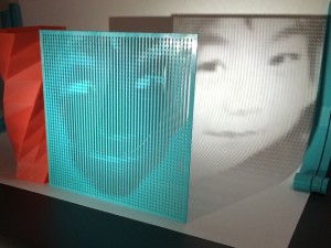
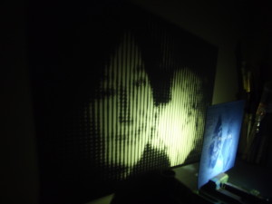
The script isn’t very efficient – it evidently takes hours to process images much larger than the icon-sized 20×20 default – but it is rewarding to see people use it nonetheless. Here are two beautiful examples, both modified to print higher resolution images:
Posted on Monday, April 7th, 2014.
F-86
Today I printed this airplane model designed by Dolf Veenvliet, based on the F-86 Sabrejet.
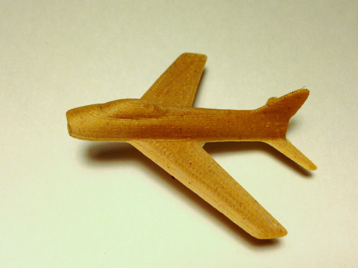
Thanks to my dad for the link. My grandfather’s unit, the Boys from Syracuse, flew the F-86. Today was his birthday.
Posted on Wednesday, March 26th, 2014.