PrintrBot Assembly Notes
The Printrbot Simple’s assembly instructions are published online as a photo-illustrated guide. Having recently assemble my own Printrbot, I thought I would share a few comments and tips for the benefit of anyone else about to build one.
First, and most generally, it’s worth reading through the instructions before you begin building to get a sense of how everything it will fit together. At the very least, look at the photos for the next step before you proceed with the current step to see how the current step will look when done.
Find the right tool for the job of separating the laser-cut plywood parts (step 2). I did not settle on a safe and consistent cutting method until I tried the chisel-tip blade pictured at right. (Simply snapping the parts apart by hand is possible, but discouraged due to the possibility of splitting or snapping the parts themselves.) This advice may soon be moot since I understand Printrbot plans to transition to all-aluminum construction.
The zip ties securing the Z axis drive rod coupler (step 40) pass very close to wires from the circuit board. I wrapped a piece of tape around the zip tie nubs to prevent them from accidentally yanking wires as the rod rotates. Careful grouping and routing of wires is general good practice to avoid interference with moving parts.
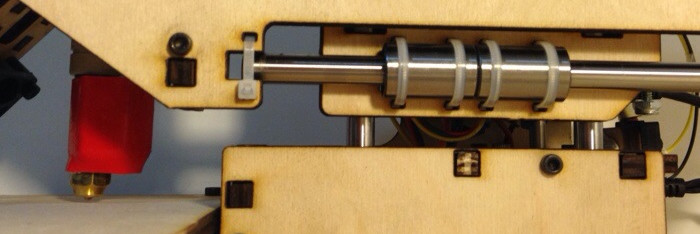
Last but most important: once you’ve finished the assembly, but before you run the printer for the first time, examine the 3″ bolt installed on the back of the extruder carraige in step 30. This is the Z stopper. Its job is to hit the Z end stop switch on the base of the printer (nut and black box at right in the picture above) just before the extruder tip hits the print bed (at left in the picture above). Make sure it is threaded in far enough to do so! Otherwise, the extruder tip will be driven into the print bed when the printer attempts to find its “home” location by descending until the Z stop is triggered.
Posted on Wednesday, January 22nd, 2014.