Tag Archive: “LEGO”
How to Build LPub
LPub is a program by Kevin Clague which you can use to create building instructions from LDraw models. If you are eager to test out features that are still in development, you will need to compile it yourself. Here’s how!
Install Qt
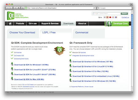
Qt is an interface toolkit and application framework. The current version of LPub requires Qt 4.5. I downloaded the LGPL/Free version of the Qt SDK for Mac (436 Mb). Installation is easy: just double-click the installer package and accept the default settings.
Download the LPub Code
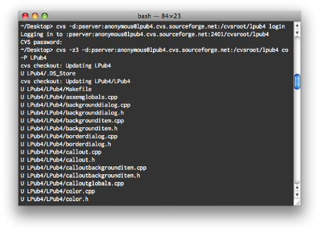
Fire up Terminal and navigate to an appropriate place to store your files (probably not the Desktop). Check out a fresh copy of the LPub source code with the following two commands (just press enter when prompted for a password):
cvs -d:pserver:anonymous@lpub4.cvs.sourceforge.net:/cvsroot/lpub4 login
cvs -z3 -d:pserver:anonymous@lpub4.cvs.sourceforge.net:/cvsroot/lpub4 co -P LPub4
This will result in an LPub4 folder containing everything you need. To update your working copy of the code with any recent changes, issue the following command from anywhere within the LPub4 folder:
cvs update
Compile LPub
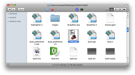
Navigate to the innermost LPub4 directory, create a Makefile for your machine, and compile the program with the following commands:
cd LPub4/LPub4
/usr/bin/qmake -spec /usr/local/Qt4.5/mkspecs/macx-g++ -macx -o Makefile LPub.pro
make
After updating from previous versions of LPub, you may occasionally find it necessary to delete the com.lpub.LDraw Building Instruction Tool.plist file from your ~/Library/Preferences directory.
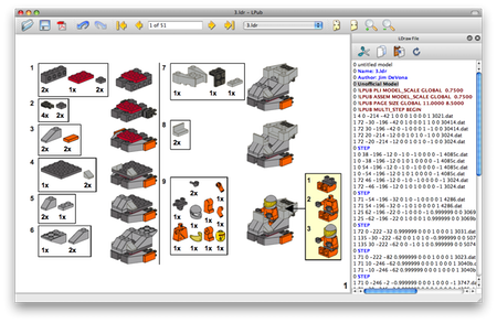
Test and Provide Feedback
Now you’re ready to experiment with the latest LPub technology. Make some custom instructions! (Explaining the ins and outs of the program itself is a subject for another post.)
Your work is not done yet, though: an important part of playing with unreleased software, in my opinion, is to provide feedback to the developer (even if you are not a programmer, your input can be very useful). Offer detailed descriptions of any bugs you encounter, cogent suggestions for improvements, and thanks to folks like Kevin for investing so much effort in programs like LPub.
Posted on Saturday, May 16th, 2009. Tags: LDraw, LEGO, lpub.
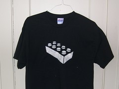
My LEGO Shirt
I made a stencil of the basic LEGO brick and spray-painted it on a T-shirt. It’s pretty rad.
Posted on Thursday, May 7th, 2009. Tags: LEGO.
Bricksmith Custom Categories
Here is a hack to add new categories to the Bricksmith part browser. The part catalog is normally organized into categories based on the type of each part (such as brick, plate, or tile). However, if you’re building a model based on a real set, it’s just as useful to present the parts from that set in one category.
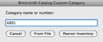
Adding a category from a Peeron inventory
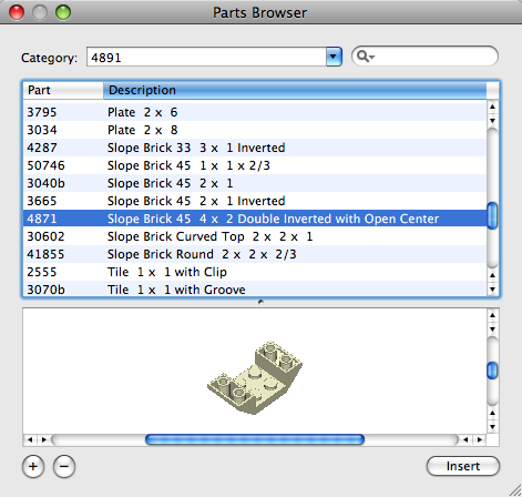
To create a category consisting of the parts from set 4891, enter 4891 and click Peeron Inventory:
The script will retrieve the corresponding list of parts and populate a new category containing them:
Adding a category from a file
To create a category based on an arbitrary group of parts, save a list of part file names, like this:
3005.dat
3004.dat
3003.dat
3001.dat
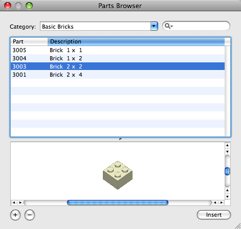
Then enter a name for your category and click From File. You’ll be prompted to select the list you just created.

The script will add the listed parts to the named category:
Limitations
The script is awfully slow. AppleScript’s property list commands are not well suited for making many changes.
Parts listed in the file or inventory which are not already present in your part library will not be included in the category.
New categories are not visible until you restart Bricksmith. (I recommend quitting Bricksmith before running the script anyway.) Custom categories are lost when you reload the part list from Bricksmith’s Parts preferences.
No feedback is provided while the script is running.
Errors are not handled particularly well.
Mac OS X 10.5 is required.
It’s really slow.
Download
Bricksmith Catalog Custom Categories 26.4 KB
Posted on Saturday, June 21st, 2008. Tags: applescript, bricksmith, LDraw, LEGO.
LDTrim
LDTrim is a simple program that condenses or formats LDraw code by trimming extraneous characters like spaces – or inserting them to align values in columns.
LDTrim was developed to help “pretty-print” examples for documentation or discussion, but it could also be used to reduce file size or to standardize the format of many models.
Much of what LDTrim does is already possible with LDraw Design Pad. For example, see “Trim Lines” and “Auto Round Selection” under the “Tools” menu.
Usage
Here is the output of ldtrim -help:
LDTrim 1.1
Usage: ldtrim                         Default:
    [-in FILE]  | [-in FILE FILE...]    stdin (use -ing to glob wildcards)
    [-out FILE] | [-out DIRECTORY]      stdout
    [-precision DIGITS]                 all significant digits preserved
    [-trim zeros|none]                  zeros (trims redundant trailing zeros)
    [-justify left|right|none]          none (alignment of values in field)
    [-invalid omit|keep]                omit (keep retains unrecognized lines)
    [-width CHARACTERS|max]             variable (minimum width of all fields)
    [-1..15 CHARACTERS]                 variable (override width for one field)
    [-h|--h|-help|--help]               display this usage summary

If multiple input files are specified without -out, they are modified in place.
If -out is given with multiple input files, output is saved to that directory.

The -precision option causes values to be rounded down and may append zeros to
reach the specified precision unless -trim zeros is explicitly specified.

Whitespace between fields is condensed to a single space.

The -width option pads values with spaces to reach the specified field width.
If -width max is given, the widest value is used as the width for all fields.
(Sub-part names are ignored for this comparison.) If a field value exists that
is wider than the requested width, that width is used as the field width.

Right justification is used if -width or -1..15 is specified without -justify.
If none of -width, -1..15, or -justify is specified, fields are unaligned.

If environment variable GATEWAY_INTERFACE is defined, LDTrim is a CGI script.
Example
Suppose you have saved this LDraw code as sample.ldr:
1 0 20.000000 0.000000 20.000000 0.000000 -1.000000 0.000000 1.000000 0.000000 0.000000 0.000000 0.000000 1.000000 4085c.dat 1 1 28.000000 7.000000 27.000000 0.000000 -1.000000 0.000000 0.500000 0.000000 -0.866025 0.866025 0.000000 0.500000 3023.dat 1 25 36.000000 -5.000000 11.000000 0.000000 -1.000000 0.000000 0.707106 0.000000 -0.707106 0.707106 0.000000 0.707106 2412b.dat Running ldtrim -in sample.ldr -out trimmed.ldr will save the following as trimmed.ldr:
1 0 20 0 20 0 -1 0 1 0 0 0 0 1 4085c.dat 1 1 28 7 27 0 -1 0 0.5 0 -0.866025 0.866025 0 0.5 3023.dat 1 25 36 -5 11 0 -1 0 0.707106 0 -0.707106 0.707106 0 0.707106 2412b.dat The default behavior is to condense the code as much as possible without modifying the model. Alternatively, you can use LDTrim to reformat code. For instance, ldtrim -precision 2 -width 5 -1 1 -2 3 -in trimmed.ldr -out aligned.ldr outputs the following as aligned.ldr:
1 0 20.00 0.00 20.00 0.00 -1.00 0.00 1.00 0.00 0.00 0.00 0.00 1.00 4085c.dat 1 1 28.00 7.00 27.00 0.00 -1.00 0.00 0.50 0.00 -0.87 0.87 0.00 0.50 3023.dat 1 25 36.00 -5.00 11.00 0.00 -1.00 0.00 0.71 0.00 -0.71 0.71 0.00 0.71 2412b.dat Giving a minimum field -width argument implies -justify right. Similarly, decimal -precision implies -trim none, leaving trailing zeros intact. The -1 and -2 options override the minimum width for the first two columns.
Batch Mode
If LDTrim is given multiple input files, it will process them all, saving the results to files of the same name in the directory given by -out or overwriting the input files if no output folder is given.
ldtrim -in $LDRAWDIR/parts/*.dat -out /trimmed/parts/ Note that with a single -in file, -out is interpreted as a single output file, but with multiple -in files, -out is interpreted as a directory to contain the results.
Web Interface
LDTrim has a rudimentary web interface built in. If the GATEWAY_INTERFACE environment variable is detected, LDTrim will behave like a CGI script. Specifically, it will print an HTML form with controls that roughly correspond to its command-line options. LDraw code posted via this form (to itself, as the action ldtrim) is processed according to the selected options. The results are returned in the same form.
Download
LDTrim is also available as a platform-independent Starkit (50 KB) which requires an 8.5 Tclkit.
- Mac OS X 2.4 MB
- Linux (x86) 1.5 MB
- Windows 686 KB
The current version of LDTrim is 1.1; it fixes a bug that caused malformed line endings to be output on Windows.
Posted on Saturday, May 10th, 2008. Tags: LDraw, LEGO, tcl.
LDraw Part Search Services
Just some handy reference tools for the discerning LDraw hobbyist. Quickly access information about selected parts from any application.
Download LDraw Part Search Services 127k
Four popular databases are currently supported: Bricklink, the LDraw Parts Tracker, Lugnet Partsref, and Peeron.
Posted on Thursday, November 8th, 2007. Tags: LEGO.
Instruction Step Fading with PreL3P
By substituting different colors in different parts of a model, PreL3P can be used to create interesting effects such as the step-by-step highlighting seen here:
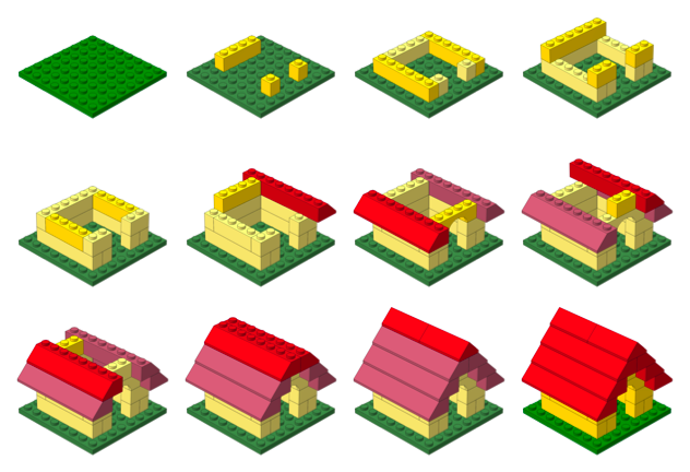
This page explains how this image was created. It is intended as a demonstration of what can be done with PreL3P, but other relevant topics are discussed. Windows users may be interested in LPub as a more convenient solution.
Color Preparation
Two sets of color code definitions are needed to achieve this effect. A set of modified colors is used first to give parts from previous steps a faded appearance. Then a set of normal colors is loaded to give new parts their vivid hue.
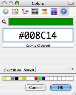
Here are the normal colors from ldconfig.ldr used to draw the current step and the final image:
0 normal.ldr
0 !COLOUR Green  CODE  2 VALUE #008C14 EDGE 0
0 !COLOUR Red    CODE  4 VALUE #C40026 EDGE 0
0 !COLOUR Yellow CODE 14 VALUE #FFDC00 EDGE 0
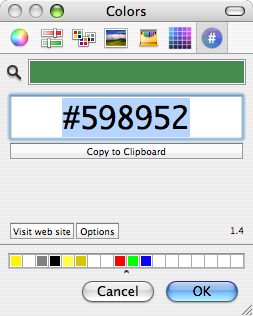
I used Hex Color Picker along with the standard HSB saturation slider to choose faded versions of these colors. You can use the color picker from any application to do this.
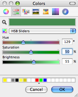
Of course, this approach is not practical for converting large numbers of colors. You’ll have to devise your own system for selecting and generating suitable substitute colors.
Here are the faded colors used for parts from previous steps:
0 faded.ldr
0 !COLOUR Green  CODE  2 VALUE #598952 EDGE 0
0 !COLOUR Red    CODE  4 VALUE #B26676 EDGE 0
0 !COLOUR Yellow CODE 14 VALUE #FBEC87 EDGE 0
Steps
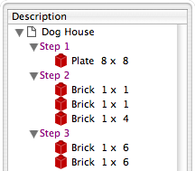
The STEP meta command marks the end of each instruction step in an LDraw model. For example, here are the first three steps of the doghouse model pictured above:
1 2 0 0 0 1 0 0 0 1 0 0 0 1 41539.dat
0 STEP
1 14 50 -24 30 -1 0 0 0 1 0 0 0 -1 3005.dat
1 14 50 -24 -30 -1 0 0 0 1 0 0 0 -1 3005.dat
1 14 -50 -24 0 0 0 -1 0 1 0 1 0 0 3010.dat
0 STEP
1 14 0 -24 50 1 0 0 0 1 0 0 0 1 3009.dat
1 14 0 -24 -50 1 0 0 0 1 0 0 0 1 3009.dat
0 STEP
Most LDraw editors make it easy to create and organize steps. For instance, steps are always shown as part of the model hierarchy in Bricksmith’s “File Contents” drawer:
Once a model is complete, its constituent steps can be exported as a series of individual files that represent the model up to that point. In other words, each exported step model is essentially identical to the original model except that it is truncated after the corresponding step.
Rendering each of these partial models produces an image depicting each step in the instructions.
PreL3P Meta Commands
Before proceeding to render the step models, PreL3P meta commands are inserted at the beginning of the file and at the beginning of the most recent step to invoke the appropriate color substitution schemes. The -ldconfig option is used to load the faded.ldr and normal.ldr files prepared above. (PreL3P supports the notion of “LDraw configuration files”—files containing pertinent meta commands; if present, any visible linetypes are ignored.)
By default, PreL3P does not modify the basic color codes understood by L3P. To accomplish step fading, however, it may be necessary to do so. The +codes option tells PreL3P which color codes should be kept in their original form. The special parameter none causes all codes to be converted.
Here is the third step model with meta commands inserted:
0 !PREL3P +codes none
0 !PREL3P -ldconfig faded.ldr
1 2 0 0 0 1 0 0 0 1 0 0 0 1 41539.dat
0 STEP
1 14 50 -24 30 -1 0 0 0 1 0 0 0 -1 3005.dat
1 14 50 -24 -30 -1 0 0 0 1 0 0 0 -1 3005.dat
1 14 -50 -24 0 0 0 -1 0 1 0 1 0 0 3010.dat
0 STEP
0 !PREL3P -ldconfig normal.ldr
1 14 0 -24 50 1 0 0 0 1 0 0 0 1 3009.dat
1 14 0 -24 -50 1 0 0 0 1 0 0 0 1 3009.dat
For each successive step the -ldconfig normal.ldr line should be inserted later in the file. If your editor includes the STEP lines in exported step models, it is fairly easy to locate the beginning of the last step. The correct location can also be found by comparing each step model file to the previous step’s file; the new step starts where the files differ. This is the method used by Travis Cobbs’ shell script.
The first step is a special case since there are no previous steps that need to be faded. You may be able to render it without modification. For consistency, however, you could load the standard color set at the beginning of the file:
0 !PREL3P +codes none
0 !PREL3P -ldconfig normal.ldr
1 2 0 0 0 1 0 0 0 1 0 0 0 1 41539.dat
Note that the preparations are slightly more complex for MPD files. Another -ldconfig faded.ldr command would be needed at the end of the main model to draw submodels from previous steps in the faded colors. Any submodels included in the current step would need to use normal.ldr again. Submodels referenced by the previous step and the current step present a challenge that is left as an exercise for the reader.
Running PreL3P
Once the meta commands have been inserted, the step models can be processed with PreL3P. This replaces the original color codes with hexadecimal values that represent the exact shades defined in the color configuration files.
prel3p -in doghouse3.ldr -out doghouse3-faded.ldr
Rendering
Finally the faded step models are ready to be rendered. PreL3P’s name is a bit of a misnomer; the output works just as well with LDView (note, however, that these hexadecimal colors do not conform to the LDraw format specification, so don’t expect them to work with all LDraw software).
Currently, it is easiest to render a batch of images from the command line. If you save a bunch of command lines to a file named render, you can run them all with sh render (other automation methods may be forthcoming). Here’s what one command looks like:
ldview doghouse3.ldr -SaveSnapshot=doghouse03.png -AutoCrop=0 -SaveZoomToFit=0 -WindowWidth=1024 -WindowHeight=1024 -SaveActualSize=1 -cg30,45 -ModelCenter=0.0,-50,0.0 -ModelSize=250
With LDView 3.2 on Mac OS X, you might need to expand ldview to /Applications/LDView/LDView.App/Contents/MacOS/LDView. Only the first two arguments need to be changed from step to step; the rest specify the size of the output image and ensure that each image will be rendered at the same scale. I’m not particularly familiar with LDView’s command line syntax, so more succinct options may be possible.
Briefly, the -cg option specifies the “latitude and longitude” of the camera on a globe whose origin is specified in LDraw units by the -ModelCenter option. The -ModelSize option controls the distance from the camera to the center of the model. These options work together to ensure the same perspective is used to depict each step. Otherwise, the different dimensions of the individual steps might result in inconsistent default camera positions.
Posted on Friday, October 19th, 2007. Tags: l3p, LDraw, LEGO, prel3p, tcl.
PreL3P
PreL3P preprocesses LDraw files for color compatibility with L3P, which converts LDraw models to POV-Ray format. The current version of L3P (1.3) only knows about some color codes, but it does support arbitrary colors via an extended color syntax. PreL3P replaces LDraw color codes unrecognized by L3P with hexadecimal “extended color” specifications based on the COLOUR definitions provided by your LDraw configuration file. No special material tags are honored besides ALPHA 128 (regular transparency). Color codes can also be mapped directly to other color codes.
PreL3P is a hack to allow models containing contemporary colors to be rendered with L3P and POV-Ray without touching any POV-Ray code. It is not intended to replace other, more expert, solutions to the color quandary; better results can arguably be had by manually including custom POV-Ray color definitions. Ideally, L3P and other programs like Bricksmith would support ldconfig.ldr themselves.
Usage
prel3p # Default: [-in FILE] # stdin [-out FILE] # stdout [-ldconfig FILE] # LDRAWDIR/ldconfig.ldr [+codes none|l3p|CODE[,...]] # l3p (keep codes known by L3P) [-codes none|l3p|CODE[,...]] # none (preprocess all others) [-map IN:OUT] # no mappings [-flag quiet] # not quiet (report completion) [-flag noglob] # glob expansion supported [FILE[,...]] # none (see Alternate Usage) Explicit option values override the defaults.
PreL3P can be used as a filter:
prel3p < input.ldr > output.ldr Output is not written until the input has been successfully parsed and processed, so files can be preprocessed in place:
prel3p -in model.ldr -out model.ldr The codes options permit custom substitution schemes to be specified. The + and - characters represent color codes which should be preserved and color codes which may be replaced, respectively.
prel3p +codes 0 # replace any code other than 0 (black) prel3p -codes 0,71,72 # replace codes 0, 71, and 72, but no others prel3p +codes l3p -codes 4 # preserve color codes known to L3P, except 4 prel3p +codes none # replace every color code (preserve none) Unspecified codes are handled according to the behavior implied by the type of the first codes option. +codes implies that other codes may be replaced; -codes implies that other codes should be preserved. Subsequent options of either type modify the initial set.
Color codes can be renumbered with the -map option. For instance, to replace instances of color code 7 with color 8, specify -map 7:8. Mapping occurs before substitution, so if -codes 8 is also specified and a !COLOUR definition for 8 is found, instances of 7 will ultimately be replaced by the hexadecimal equivalent of 8.
A message reporting how many colors were changed and how many lines contained changes is printed when processing is complete. Mappings and color substitutions both constitute color changes.
Color definitions are normally read from LDRAWDIR/ldconfig.ldr (LDRAWDIR is an environment variable assumed to contain the path to your LDraw directory). Different configuration files may be specified with the -ldconfig option. Multiple -ldconfig options may be given, in which case the last of multiple definitions for the same color code takes precedence.
With the exception of color codes, PreL3P’s output is identical to its input. Whitespace, capitalization, and decimal precision are not modified. Unrecognized lines are preserved, as are unrecognized color codes (those not identified by the ldconfig file).
Alternate Usage
If no -in or -out arguments are specified, PreL3P will interpret unrecognized arguments as paths to files to process.
prel3p model.ldr The original model.ldr is copied to model.ldr.bak and the processed version is saved in place as model.ldr.
In this context PreL3P understands glob wildcard characters. For instance, in a directory containing only the files model1.ldr, model2.ldr, and model3.ldr, the following commands are equivalent:
prel3p model*.ldr prel3p model?.ldr prel3p model[1-3].ldr prel3p model{1,2,3}.ldr prel3p model1.ldr model2.ldr model3.ldr This feature is intended primarily as a convenience for Windows command prompt users since this functionality is typically provided by the command line shell itself on other platforms (unless the argument is quoted). Wildcard expansion can be disabled with the -flag noglob option.
Meta Commands
In addition to the !COLOUR meta command, PreL3P understands unofficial meta commands which allow certain PreL3P command line options to be imbedded in models and configuration files.
The general form of these meta commands is:
0 !PREL3P OPTION VALUE where OPTION is one of -ldconfig, +codes, -codes, or -map and VALUE is formatted as the analogous command line parameter.
Options and !COLOUR definitions are read from the input model header after command line options are parsed. The model header is comprised of all input lines preceding the first instance of any LDraw type 1 through 5 lines. Configuration files specified by -ldconfig options in the model header are appended to the configuration file queue and override the default -ldconfig if no explicit value is given on the command line.
Configuration files are parsed sequentially after reading the model header. The entire configuration file is read; LDraw type 1 through 5 lines are ignored. Additional configuration files specified by -ldconfig meta commands within configuration files are parsed at the point they are encountered.
PreL3P meta commands in the model that are not in the model header are parsed and applied as they are encountered during processing. This allows different color substitution schemes to be used for different parts of the model.
Example
Here is a simple LDraw file, bricks.ldr. It uses color codes 89 (Royal Blue), 92 (Flesh), and 72 (Dark Stone Gray).
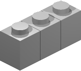
1 89 0 0 -20 1 0 0 0 1 0 0 0 1 3005.dat 1 92 0 0 0 1 0 0 0 1 0 0 0 1 3005.dat 1 72 0 0 20 1 0 0 0 1 0 0 0 1 3005.dat L3P doesn’t recognize these color codes, so it replaces them with the default color 7 (Gray). As a result, the initial rendering looks like this:
So, let’s use PreL3P to make a copy of the model with colors L3P can understand:
prel3p -in bricks.ldr -out prebricks.ldr The contents of prebricks.ldr:
1 0x029BB2EF 0 0 -20 1 0 0 0 1 0 0 0 1 3005.dat 1 0x02CC8E68 0 0 0 1 0 0 0 1 0 0 0 1 3005.dat 1 0x02635F61 0 0 20 1 0 0 0 1 0 0 0 1 3005.dat L3P converts this version of the model without complaint, and the final rendering looks like this:

Changes
1.1:
- Added “done” announcement and statistics with complementary
-flag quietoption. - Multiple
-ldconfig FILEoption pairs may be given. - Added alternate usage syntax.
1.2:
- Added
-mapoption to convert color codes directly to other codes. - Added
!PREL3Pmeta command versions of-ldconfig,+code,-codes, and-map. - Added
-helpoption to display brief usage summary. - Tweaked alternate usage backup mechanism.
1.3:
- Meta commands may be used throughout models.
1.3.1:
- Properly report a few errors.
- Limit number of
-ldconfigreferences to prevent circular references.
1.4:
- Added ability to process multiple files
- Added support for wildcard characters
Download
- prel3p-1.4-kit.zip 14 KB
Platform independent Starkit. Requires a separate Tclkit (8.4.16 recommended). - prel3p-1.4-mac.zip 1.9 MB
Self-contained universal binary (x86 + PPC) for Mac OS X 10.4+. - prel3p-1.4-mac-service.zip 2 MB
Macintosh Starpack bundled as a service for filtering selected text. Install in~/Library/Services/. - prel3p-1.4-win.zip 559 KB
Self-contained console binary for Windows.
The source code may be extracted from any version with SDX. An example localization file is available here.
Posted on Saturday, October 6th, 2007. Tags: l3p, LDraw, LEGO, prel3p, tcl.
LDMerge
LDMerge is a console program for merging and unmerging the contents of multiple LDraw directory structures. Multiple part libraries may be used to manage unofficial parts. Some LDraw-compatible programs support this concept, but others do not. By providing a way to temporarily combine several part libraries, this utility facilitates those tools which recognize only a single LDraw directory — without forcing you to adopt the same convention.
Unlike its predecessor LDLink, LDMerge does not rely on symbolic links.
Overview
LDMerge performs two actions: merge and unmerge.
Both actions are applied to a target library. Merging adds parts to the target libary and unmerging removes those parts from the target library.
A source library provides the parts that are merged. More than one source can be merged into the same target. Parts from all sources or from one particular source can be unmerged.
An index file records the source of each merged part.
LDMerge considers an LDraw part library to be a directory containing the subdirectories parts, parts/s, p, and p/48. Files of any type within these subdirectories are considered parts. Other files and folders in the library but not within those specific subdirectories are ignored.
Usage
LDMerge accepts command line arguments corresponding to each of the key terms introduced above.
ldmerge merge|unmerge
        [-target LDRAWDIR]
        [-source LDRAWDIR|all]
        [-index FILE]
        [-mode copy|move|link]
        [-flag verbose]
The first argument is required and specifies the action: merge or unmerge.
If -target is not specified, the value of the LDRAWDIR environment variable is used.
If -source is not specified, it is assumed to be the target’s Unofficial subdirectory. (LDView can automatically download unofficial parts to this location.) The special all source is meaningful only when unmerging.
If -index is not specified, the file ldmerge.ldr in the target directory is used.
The -mode option allows you to specify how parts are merged. By default, part files are copied from the source to the target. If the move mode is used, the source files themselves are moved to the target directory. They are returned to the source directory when unmerged. The link mode creates symbolic links (on Mac OS X or Linux) or hard links (on Windows NTFS systems) to the source files. Moving or linking can be faster, but copying may present the fewest complications. It is not necessary to specify a -mode when unmerging.
Specify -flag verbose to print a line reporting each merge or unmerge operation.
Examples
To merge unofficial parts downloaded by LDView with the rest of your part library, the following command may be sufficient:
ldmerge merge
That copies each part from LDRAWDIR/Unofficial to the corresponding subdirectories of LDRAWDIR, and records the merges in LDRAWDIR/ldmerge.ldr. The default merge can be reversed with the following command:
ldmerge unmerge
This merge command moves the actual source files to the target library:
ldmerge merge -source /Custom/LDraw -mode move
To restore the main library to its original state by removing all merged files, use this command (merged files will be returned to their original location if they were moved):
ldmerge unmerge -source all
A merge can be made permanent by removing the relevant lines from the merge index.
LDMerge will not replace parts in the target library unless the existing merge index indicates that they came from the current source library. Part conflicts and other recognized exceptions are reported; merging or unmerging proceeds if possible. Errors copying, moving, or linking files cause the program to stop.
Parts are identified by filename. File contents are not examined.
Index Format
The index records are formatted as LDraw meta commands. At present, this choice of format is arbitrary, but it may facilitate interesting possibilities in the future.
0 !LDMERGE /Target/LDraw/parts/part.dat SOURCE /Source/LDraw/parts/part.dat
Each record documents a merged part in the target library. The path to this part is stated after the !LDMERGE token. Subsequent parameters may appear in any order and are interpreted as “PARAMETER value” pairs. Presently only the SOURCE parameter is used; it specifies the part’s original location.
Records without SOURCE parameters are valid. They effectively “reserve” parts. If present, the part cannot be removed; if not present, the part cannot be added.
Index lines that cannot be interpreted as LDMerge records are ignored but retained. They appear before all valid records in the updated index.
Paths may contain whitespace, in which case they appear quoted in curly braces.
Downloads
LDMerge is currently available in three forms:
- ldmerge-1.1-kit.zip 8KB
Platform independent Starkit. Requires a separate Tclkit (8.4.16 recommended). - ldmerge-1.1-mac.zip 1.8MB
Self-contained universal binary (x86 + PPC) for Mac OS X 10.4+. - ldmerge-1.1-win.zip 553KB
Self-contained console binary for Windows.
The source code may be extracted from any version with SDX. LDMerge is localizable; see en_us_example.msg for more details. LDMerge is public domain software.
Changes
1.1:
- Fixed
-source all - Index and most messages use native directory separators
Posted on Monday, October 1st, 2007. Tags: LEGO, tcl.
Brickshelver Development Release
Brickshelver is a small utility I have written to simplify the process of uploading files to Brickshelf, a popular site for LEGO hobbyists.
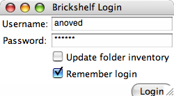
When you start Brickshelver, you log in using your Brickshelf account. Brickshelver maintains a list of your Brickshelf folders, but it takes a few moments to conduct this inventory. You can skip this step after the first run for faster logins, but in this case Brickshelver will not be aware of any new folders created via the regular web interface.
You can add files to the list of files to upload by clicking the “+” button or by dragging them to Brickshelver’s Dock icon. The files will all be uploaded to the indicated folder, which can be an existing folder or a new folder created with Brickshelver.
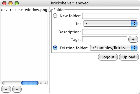
Clicking “Upload” will automatically zip the files and upload them to Brickshelf, creating a new folder if necessary. Upload status is reported in the space to the left of the “Upload” button.
Important Notes
This release consists of a stand-alone application for Mac OS X. This application exhibits many inconsistent or unconventional behaviors, as Brickshelver is actually a Tcl/Tk script bundled in a generic application wrapper. There are a large number of issues that need to be addressed and features that need to be improved, including but not limited to:
- Quit via File→Close or by closing the window, but not via Brickshelver→Quit
- Can’t drag files into the actual window
- Localization
- Layout and appearance quirks
- File type validation
- Cross platform support (specifically, zip and preferences mechanisms)
- Full paths look dopey in file list
I am content with Brickshelver in its current state, but I caution others that it is alpha quality software. Further development depends on the reaction to this release; how to proceed is clear, but I am eager to work on other projects instead.
Download Brickshelver Development Release 2.6MB .tar.gz
Your folder inventory and account information (including unencrypted Brickshelf password) are stored on your computer in ~/Library/Preferences/net.anoved.brickshelver.plist. The format of this file may change in any future releases.
Posted on Monday, August 6th, 2007. Tags: LEGO.
LDLink
Note: LDLink has been superseded by LDMerge.
LDLink is a utility that can reversibly combine separate LDraw part libraries by creating symbolic links to the contents of one directory structure in another. Alternate libraries can be used to manage unofficial LDraw parts; support for this concept is present to varying degrees in some LDraw programs. This utility is intended to facilitate other tools, such as L3P, which do not readily support parallel part libraries.
Download ldlink 1.0 (5k Tcl script)
Install the script as ldlink and make it executable with chmod +x ldlink.
Usage: ldlink merge|unmerge [-src LDRAWDIR] [-dst LDRAWDIR]
       On merge, links to src files are created in dst.
       On unmerge, links named after src files are removed from dst.
       Conflicts with normal files in dst are skipped and reported.
       Default dst is LDRAWDIR environment variable.
       Default src is dst/Unofficial.
To merge unofficial parts downloaded by LDView with the rest of your part library, the following command may be sufficient:
ldlink merge
If the environment variable LDRAWDIR is not defined — or if you would like to override its value — use the dst option to specify the destination where the merge should occur. Likewise, the src option may be used to merge parts from a source other than the destination’s Unofficial subdirectory:
ldlink merge -src /Custom/LDraw -dst /Standard/LDraw
To reverse a merge, reissue the command using unmerge instead of merge:
ldlink unmerge
ldlink unmerge -src /Custom/LDraw -dst /Standard/LDraw
LDLink reports how many links it created or removed.
Posted on Tuesday, July 10th, 2007. Tags: LEGO.