Instruction Step Fading with PreL3P
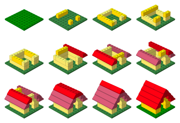
By substituting different colors in different parts of a model, PreL3P can be used to create interesting effects such as the step-by-step highlighting seen here:
This page explains how this image was created. It is intended as a demonstration of what can be done with PreL3P, but other relevant topics are discussed. Windows users may be interested in LPub as a more convenient solution.
Color Preparation
Two sets of color code definitions are needed to achieve this effect. A set of modified colors is used first to give parts from previous steps a faded appearance. Then a set of normal colors is loaded to give new parts their vivid hue.
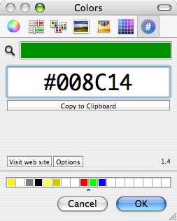
Here are the normal colors from ldconfig.ldr used to draw the current step and the final image:
0 normal.ldr
0 !COLOUR Green  CODE  2 VALUE #008C14 EDGE 0
0 !COLOUR Red    CODE  4 VALUE #C40026 EDGE 0
0 !COLOUR Yellow CODE 14 VALUE #FFDC00 EDGE 0
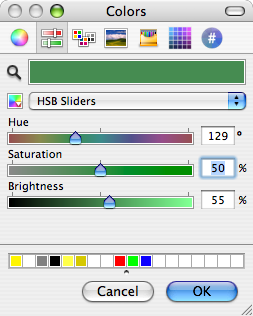
I used Hex Color Picker along with the standard HSB saturation slider to choose faded versions of these colors. You can use the color picker from any application to do this.
Of course, this approach is not practical for converting large numbers of colors. You’ll have to devise your own system for selecting and generating suitable substitute colors.
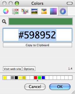
Here are the faded colors used for parts from previous steps:
0 faded.ldr
0 !COLOUR Green  CODE  2 VALUE #598952 EDGE 0
0 !COLOUR Red    CODE  4 VALUE #B26676 EDGE 0
0 !COLOUR Yellow CODE 14 VALUE #FBEC87 EDGE 0
Steps
The STEP meta command marks the end of each instruction step in an LDraw model. For example, here are the first three steps of the doghouse model pictured above:
1 2 0 0 0 1 0 0 0 1 0 0 0 1 41539.dat
0 STEP
1 14 50 -24 30 -1 0 0 0 1 0 0 0 -1 3005.dat
1 14 50 -24 -30 -1 0 0 0 1 0 0 0 -1 3005.dat
1 14 -50 -24 0 0 0 -1 0 1 0 1 0 0 3010.dat
0 STEP
1 14 0 -24 50 1 0 0 0 1 0 0 0 1 3009.dat
1 14 0 -24 -50 1 0 0 0 1 0 0 0 1 3009.dat
0 STEP
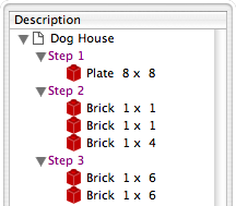
Most LDraw editors make it easy to create and organize steps. For instance, steps are always shown as part of the model hierarchy in Bricksmith’s “File Contents” drawer:
Once a model is complete, its constituent steps can be exported as a series of individual files that represent the model up to that point. In other words, each exported step model is essentially identical to the original model except that it is truncated after the corresponding step.
Rendering each of these partial models produces an image depicting each step in the instructions.
PreL3P Meta Commands
Before proceeding to render the step models, PreL3P meta commands are inserted at the beginning of the file and at the beginning of the most recent step to invoke the appropriate color substitution schemes. The -ldconfig option is used to load the faded.ldr and normal.ldr files prepared above. (PreL3P supports the notion of “LDraw configuration files”—files containing pertinent meta commands; if present, any visible linetypes are ignored.)
By default, PreL3P does not modify the basic color codes understood by L3P. To accomplish step fading, however, it may be necessary to do so. The +codes option tells PreL3P which color codes should be kept in their original form. The special parameter none causes all codes to be converted.
Here is the third step model with meta commands inserted:
0 !PREL3P +codes none
0 !PREL3P -ldconfig faded.ldr
1 2 0 0 0 1 0 0 0 1 0 0 0 1 41539.dat
0 STEP
1 14 50 -24 30 -1 0 0 0 1 0 0 0 -1 3005.dat
1 14 50 -24 -30 -1 0 0 0 1 0 0 0 -1 3005.dat
1 14 -50 -24 0 0 0 -1 0 1 0 1 0 0 3010.dat
0 STEP
0 !PREL3P -ldconfig normal.ldr
1 14 0 -24 50 1 0 0 0 1 0 0 0 1 3009.dat
1 14 0 -24 -50 1 0 0 0 1 0 0 0 1 3009.dat
For each successive step the -ldconfig normal.ldr line should be inserted later in the file. If your editor includes the STEP lines in exported step models, it is fairly easy to locate the beginning of the last step. The correct location can also be found by comparing each step model file to the previous step’s file; the new step starts where the files differ. This is the method used by Travis Cobbs’ shell script.
The first step is a special case since there are no previous steps that need to be faded. You may be able to render it without modification. For consistency, however, you could load the standard color set at the beginning of the file:
0 !PREL3P +codes none
0 !PREL3P -ldconfig normal.ldr
1 2 0 0 0 1 0 0 0 1 0 0 0 1 41539.dat
Note that the preparations are slightly more complex for MPD files. Another -ldconfig faded.ldr command would be needed at the end of the main model to draw submodels from previous steps in the faded colors. Any submodels included in the current step would need to use normal.ldr again. Submodels referenced by the previous step and the current step present a challenge that is left as an exercise for the reader.
Running PreL3P
Once the meta commands have been inserted, the step models can be processed with PreL3P. This replaces the original color codes with hexadecimal values that represent the exact shades defined in the color configuration files.
prel3p -in doghouse3.ldr -out doghouse3-faded.ldr
Rendering
Finally the faded step models are ready to be rendered. PreL3P’s name is a bit of a misnomer; the output works just as well with LDView (note, however, that these hexadecimal colors do not conform to the LDraw format specification, so don’t expect them to work with all LDraw software).
Currently, it is easiest to render a batch of images from the command line. If you save a bunch of command lines to a file named render, you can run them all with sh render (other automation methods may be forthcoming). Here’s what one command looks like:
ldview doghouse3.ldr -SaveSnapshot=doghouse03.png -AutoCrop=0 -SaveZoomToFit=0 -WindowWidth=1024 -WindowHeight=1024 -SaveActualSize=1 -cg30,45 -ModelCenter=0.0,-50,0.0 -ModelSize=250
With LDView 3.2 on Mac OS X, you might need to expand ldview to /Applications/LDView/LDView.App/Contents/MacOS/LDView. Only the first two arguments need to be changed from step to step; the rest specify the size of the output image and ensure that each image will be rendered at the same scale. I’m not particularly familiar with LDView’s command line syntax, so more succinct options may be possible.
Briefly, the -cg option specifies the “latitude and longitude” of the camera on a globe whose origin is specified in LDraw units by the -ModelCenter option. The -ModelSize option controls the distance from the camera to the center of the model. These options work together to ensure the same perspective is used to depict each step. Otherwise, the different dimensions of the individual steps might result in inconsistent default camera positions.
Posted on Friday, October 19th, 2007. Tags: l3p, LDraw, LEGO, prel3p, tcl.